 English
 русский

Slider of side core pulling mechanisum assembling
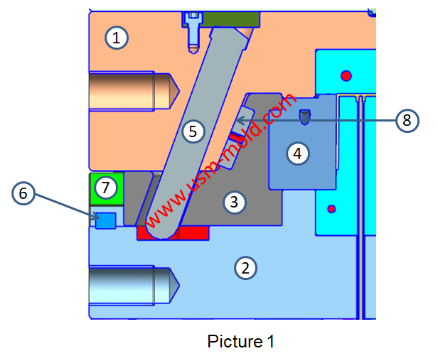
The picture 1 shows a typical guide pin driven slider parting and core-pulling mechanism, we will talk about the composition and function of the lateral core-pulling mechanism.
1. Lateral forming parts: the lateral forming part is the lateral concavo-convex (including the side hole-shaped parts, including the lateral cores and forming blocks, etc.) of the molded plastic parts, such as the slider insert 4 in picture 1;
2. Moveable parts: moveable parts refer to the parts that install and drive the lateral forming blocks or cores and move inside the guide pin, such as the slider which shows in picture 1;
3. Transmission parts: the transmission parts refer to the parts that drive the moving parts for side parting when the mold is opened or to reset when the mold is drawn and closed, such as the inclined angular pin 5 in picture 1, the types of transmission parts are: dog-leg CAM drive, hydraulic cylinder drive, air cylinder drive, etc.;
4. Locking parts: in order to prevent the moving parts from being displaced by lateral pressure during injection, the parts set are called locking parts, such as the wedge tightening surface 8 in picture 1;
5. Limiting parts: in order to make the moving parts stay in the required position after the side parting or core pulling, to ensure that the transmission parts can be reset smoothly when the mold is closed, the moving parts must be set in the lateral direction, the limit parts at the end of parting or lateral core pulling, such as limit block 6 in picture 1;
6. Guide parts: the guide parts refer to the slider that restricts the slider to move in the correct direction when moving, as shown in the guide rails 7 in picture 2.


_20250317091228A019.jpg)
Main application of gas-assisted molding technology
Apr 7, 2022Gas-assisted molding has a particularly obvious effect on the material saving of tubular and rod-shaped plastic parts, such as car handles, seat armrests, window frames, and wood-like furniture, the...view
Five Major Steps of the Injection Mold Production Process
Dec 9, 2021Injection mold manufacturing can be roughly divided into the following steps: Process analysis of plastic products. Before the mold design, the designer should fully analyze and study whether the...view
Design principles of plastic injection mold runner system
Jan 6, 20221. Quality first The design of the gating system has a big influence on part quality, firstly the gate should be set at the easiest part of the plastic part to be removed, and at the same time, the...view
What is the side parting and core pulling mechanisms with their function?
May 31, 2022When there are holes, cavities or cores on the inside or outside of the injection-molded plastic parts that are different from the opening and closing directions of the mold, the plastic parts cannot...view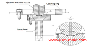
The main design points of the design of the plastic mold pouring system
Jan 11, 2022The main runner is the part where the molten plastic first passes when it is sprayed from the injection nozzle, and it is coaxial with the injection nozzle, because of repeated contact and collision...view
Conformal cooing channel of plastic injection mold
Feb 23, 2022The conformal cooling gate is a new type of mold cooling gate based on 3D printing technolog, because of its processing characteristics, the conformal cooling gate can fit the shape of the product...view