 English
 русский

Venting insert design of molded parts
In the thin-walled cavity, the end of the melt flow, the bottom of the blind hole of the mold cavity, the end of the solid column of the plastic part, the bottom of the plastic part rib and screw column, and the corners of the complex cavity are the most where it is easy to cause air trapping, the exhaust in these area mainly depends on the exhaust slot on the shut-off surface between the inserts and the exhaust slot.
Venting design of molded parts:
a. When the end of the material flow is not on the parting surface due to the restriction of the cavity structure, the matching gap between the molded parts can be used to exhaust;
b. Some parts of the forming parts that constitute the cavity, such as ejector rods, ejector pines, moveble parts, etc., the cavity or core are mostly used for clearance fit, and the matching gap is large, if it is designed in the end side of material flow, it can also serve as an exhaust gas, and there is no need to set up an exhaust system at this time;
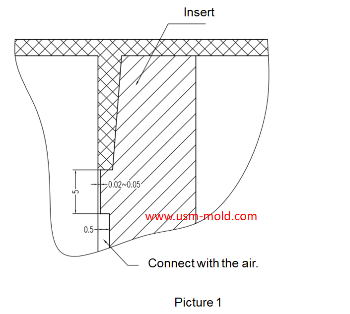
C. When the exhaust rate cannot meet the requirements, an exhaust structure can be set on the corresponding parts to increase the exhaust rate (see the picture as below);
d. The transitional fitting inserts should have an exhaust slot at the end of the material flow in advance (see the picture as below);
e. The three-stage exhaust slot must be open to the outside of the mold and connected with the air;
f. The exhaust slot between the inserts is easily blocked by plastic powder or mark, and must be cleaned regularly.

_20250310164515A048.webp "Plastic Switch Mould")

What is Ejection Molding?
Dec 28, 2021The process to get injection molded products is called injection molding, or called injection. Injection molding is an important method in polymer molding processing, it is characterized by a short...view
Controling method of plastic injection mold temperature
Feb 15, 2022Except for heat radiation and heat convection from the mold, most of the heat bring into the mold by the plastic needs to be taken out of the mold by the circulating heat transfer medium by heat...view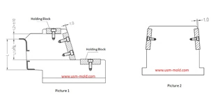
The design requirements of slider wear plate
Jan 2, 20241. The wear plate of slider requires hardening treatment, with a hardness of 45-48HRC; 2. The friction surface of the wear plate is required to be 1.0mm higher than the slider surface (see picture-1);...view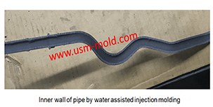
Comparison of water-assisted and gas-assisted injection molding
May 19, 2022Comparing with water-assisted injection molding technology and gas-assisted injection molding technology, the fundamental difference is the nature of the auxiliary molding media used. One is liquid...view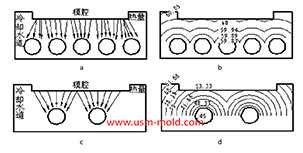
Factors affecting the cooling rate of parts by injection molding
Feb 9, 2022It should be shaped by cooling to get stable plastic part after plastic filling the cavity and core side, so most injection molds need to be equipped with cooling devices to make the mold temperature...view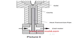
Plastic injection mold common cooling gate
Feb 17, 20221. Straight-through cooling water gate: the straight-through cooling gate is the most commonly used gate for plastic injection mold, and it is also the most convenient type of cooling for processing....view