 English
 русский

Slider spring hength and strength calculation
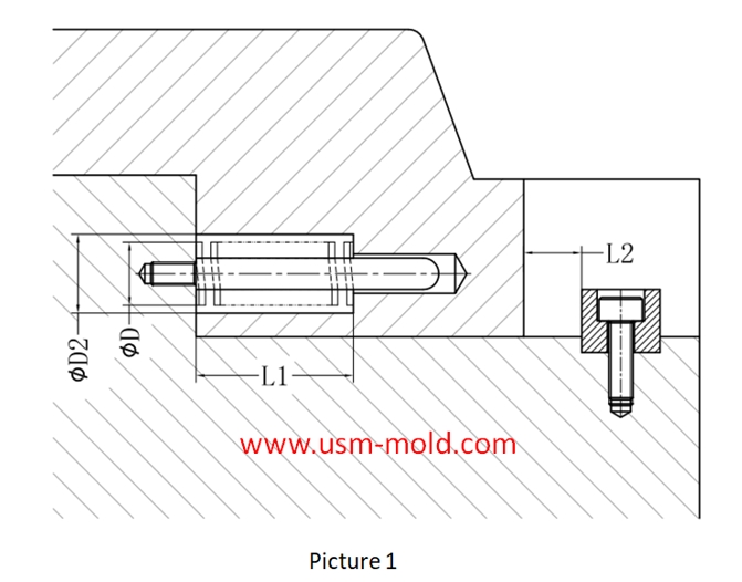
Processing size:
1. ØD2=ØD+2
2. Ll = total spring length (L) - preload value of spring (N) - slider core pulling distance (L2)
Spring length calculation: (refer to picture 1 for length calculation)
★L≥H/(36%(compression percentage)-10%(pre-compression percentage)
Assuming the core pulling distance (L2)=15m, the total length of the spring L≥15/(36%-10%)=15/0.26=57.7
As we can see that the total length of the spring (L) should be taken as 60mm
Spring hole depth L1=L-L*10%-L2=60-60*10%-15=39mm
Strength requirements of the slider spring:
1. When the spring is applied to the core pulling of the slider, the load strength must be checked;
2. The weight of the slider on the top side must be kept within 2/3 of the maximum load of the spring; the weight of other sliders must be kept within the maximum load of the spring;
3. When the same slider uses multiple springs, the maximum spring load of the slider is the sum of the loads of all springs;
4. When calculating the maximum load of the slider spring, the compression amount should be in the pull-out state of the slider;
The spring load is calculated as follows:
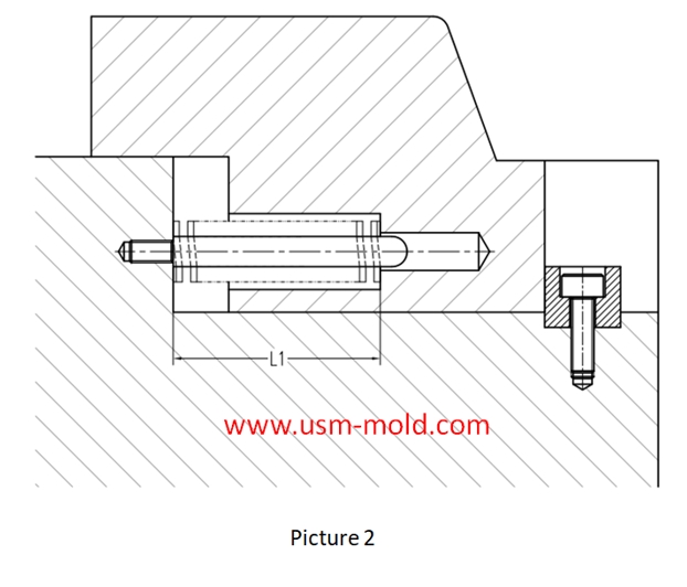
Picture 2:
1. The slider is in the extracted state, so the length of the spring after being compressed is L1;
2. Assume that the free length of the spring is L;
Calculation way of spring load: load = spring constant X compression
That is: load = spring constant X (L-L1)
The spring constant can be obtained from the standard parts data of the corresponding brand (such as MISUMI);


The air trapping position in cavity and exhaust method
Mar 2, 2022The air trapping in cavity is usually in the following places: 1. Thin-wall structure cavity, the end of melt flow; 2. The junction of two or more melts; 3. The last area where the melt in the cavity...view
Conformal cooing channel of plastic injection mold
Feb 23, 2022The conformal cooling gate is a new type of mold cooling gate based on 3D printing technolog, because of its processing characteristics, the conformal cooling gate can fit the shape of the product...view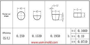
Hydraulic diameter conversion of runners in plastic mold gating system design
Jan 13, 2022Hydraulic diameter refers to 4 times the ratio of the flow cross-sectional area to the perimeter, as the wall shear stress of non-circular pipes is not even distributed along the surrounding walls,...view
Banana gate of plastic injection mold runner system design
Feb 7, 2022In order to get the best injection quality, the gate type must be selected carefully, the coommon gate tyeps are: direct gate, side gate, pin-point gate, sub gate,valve gate of hot runner etc. Among...view
Venting system of plastic injection mold introduction
Feb 27, 2022Hello everyone, thanks for attention. We’ve discussed about the temperature control system earlier, now we are going to talk about the mold venting information in following 11 articles, from the...view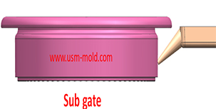
The sub gate of the plastic injection mold runner system
Jan 26, 2022In order to get the best injection quality, the gate type must be selected carefully, the coommon gate tyeps are: direct gate, side gate, pin-point gate, sub gate,valve gate of hot runner etc. Among...view