 English
 русский

The air trapping position in cavity and exhaust method
The air trapping in cavity is usually in the following places:
1. Thin-wall structure cavity, the end of melt flow;
2. The junction of two or more melts;
3. The last area where the melt in the cavity reaches;
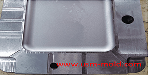
4. The bottom of the blind hole of the mold cavity is mostly the end of a solid column in the part;
5. Reinforcing ribs of molded parts and the bottom of screw pillars;
6. Dead corners of complex mold cavities.
.png)
Exhaust method in injection mold include as following:
1. Parting surface (including venting slot);
2. The fitting surface of insert;
3. The fitting surface of the push rod or pipe with inner mold insert;
4. Exhaust from side core pulling mechanism;
5. Add a vent needle or insert to vent the air in the trapped area;
6. Breathable steel exhaust;
7. Air valve exhaust;
8. The mold is evacuated and exhausted.


Venting system of plastic injection mold introduction
Feb 27, 2022Hello everyone, thanks for attention. We’ve discussed about the temperature control system earlier, now we are going to talk about the mold venting information in following 11 articles, from the...view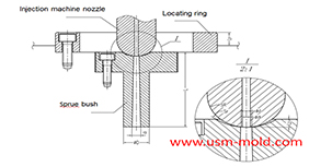
The main design points of the design of the plastic mold pouring system
Jan 11, 2022The main runner is the part where the molten plastic first passes when it is sprayed from the injection nozzle, and it is coaxial with the injection nozzle, because of repeated contact and collision...view
What is Called Draft Angle?
Dec 29, 2021The draft angle is also called demold angle and angle which is used for product removal from the mold and designed on the parting surface, the angle is called draft angle which shows in picture 1....view
Gas-assisted Injection Molding Equipment
Apr 10, 2022The gas-assisted equipment includes a gas-assisted control part and a nitrogen generator, it is special and seperate system of the injection molding machine, and its only interface with the injection...view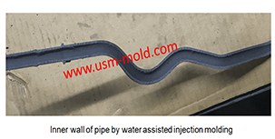
Comparison of water-assisted and gas-assisted injection molding
May 19, 2022Comparing with water-assisted injection molding technology and gas-assisted injection molding technology, the fundamental difference is the nature of the auxiliary molding media used. One is liquid...view
Banana gate of plastic injection mold runner system design
Feb 7, 2022In order to get the best injection quality, the gate type must be selected carefully, the coommon gate tyeps are: direct gate, side gate, pin-point gate, sub gate,valve gate of hot runner etc. Among...view