 English
 русский

Design standard of exhaust slot
The exhaust system should ensure that the gas in the cavity is smoothly discharged, and also prevent the material from entering and exhausting channels from causing flashing of the product or blockage of the gas channel during mass production, most plastic mold factories and plastic mold suppliers only know that they need to open an exhaust slot, but they don’t how large is reasonable. So the cross-sectional size design at the entrance of the exhaust system is very important, in order to meet the above requirements, the inlet section of the exhaust system is usually designed as a gap with a larger aspect ratio (h/w) (see pictue 1), and the gap depth (exhaust gap or exhaust slot depth) h, which is less than the overflow value of the material into the mold is limited, generally 0.02-0.05mm; the gap width w is determined according to the gap depth H and the cross-sectional area A of the exhaust passage required to discharge the gas in the mold cavity during the filling time (w≥A /h).
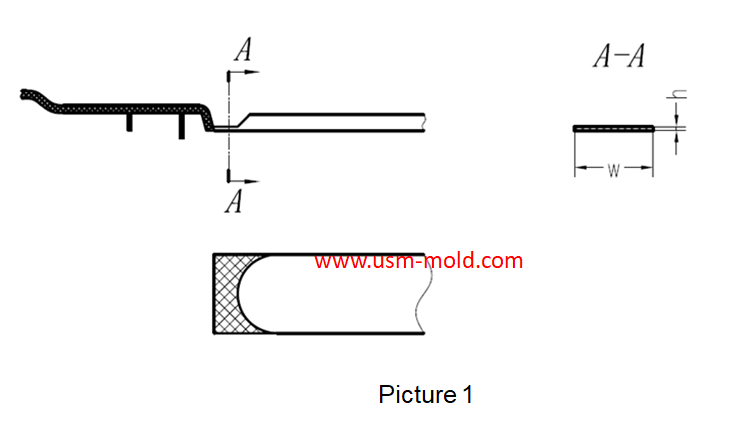
The cross-sectional area A of the exhaust channel is calculated as follows: A=0.05V/N
In the formula: A exhaust channel cross-sectional area mm²
V—total volume of cavity and pouring system, cm³
n——the number of exhaust slots
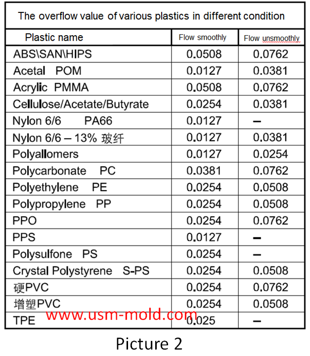
The overflow value is the smallest gap that the material can flow into, the overflow value of the molding material depends on the fluidity of the material determined by the material characteristics and process conditions. The better the fluidity, the smaller the overflow value, tThe overflow values of commonly used plastics and conventional molding conditions are shown in picture 2 in the following table.
Picure 3 shows the design standard of the exhaust slot, and picture 4 shows the wrong opening method of the exhaust slot.


Plastic injection mold cooling system design notice
Feb 14, 2022Design notice of designing the cooling system: 1. Normal molds can be quickly cooled to obtain a shorter molding cycle, and precision molds can be slowly cooled with a mold temperature thermometer; 2....view
Pin-point gate of plastic injection mold runner system design
Jan 24, 2022In order to get the best injection quality, the gate type must be selected carefully, the coommon gate tyeps are: direct gate, side gate, pin-point gate, sub gate,valve gate of hot runner etc. Among...view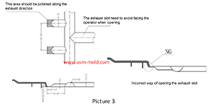
Design standard of exhaust slot
Mar 3, 2022The exhaust system should ensure that the gas in the cavity is smoothly discharged, and also prevent the material from entering and exhausting channels from causing flashing of the product or blockage...view
Temperature system of injection mold
Feb 8, 2022Hi everyone,the mold cooling time is the longest during injection, so the design of mold temperature system controlling is very important, we will talk about mold cooling, heating system in following...view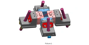
Slider designing tips 2
Nov 22, 20239. The molding parting surface of the slider molding should be made as a shut-off surface as possible, and the width of the shut-off part should be at least 8mm, and do not make a shut-off surface;...view
Key points of gas-assisted injection molding process
Apr 20, 2022Gas injection parameters The gas-assisted control part is a device that controls the gas pressure in each stage, the gas-assisted parameters have only two values: gas injection time (seconds) and gas...view