 English
 русский

Hydraulic diameter conversion of runners in plastic mold gating system design
Hydraulic diameter refers to 4 times the ratio of the flow cross-sectional area to the perimeter, as the wall shear stress of non-circular pipes is not even distributed along the surrounding walls, only the average value of the surrounding walls can be calculated.
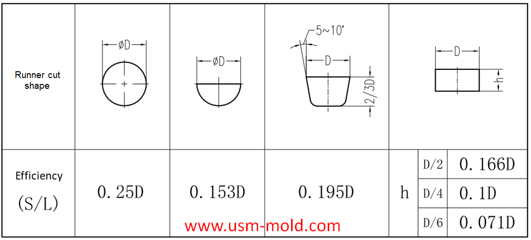
The main cross-sectional shapes of the shunt: round, trapezoidal and rectangular, in order to reduce the pressure heat loss in the runner, the cross-sectional area of the runner should be maximized, and the internal surface area for heat dissipation should be the smallest.
The efficiency of the runner is expressed by the ratio of the cross-sectional area S of the runner to its cross-sectional circumference L.
Splitter efficiency (hydraulic radius) n=cross-sectional area/cross-sectional circumference=S/L
Hydraulic diameter=4n=4S/L
From the above information, we can see the flow efficiency of different cross-section runners, round and trapezoidal cross-sections are the preferred runners. The size of the runner is usually selected based on the diameter of the circular runner (equal to the hydraulic diameter); when other cross-section flow channels are used, the hydraulic diameter must be converted so that the flow efficiency can meet the calculation requirements (see the example below) ).
Example: It is calculated that a product needs a 8m hydraulic diameter runner, and a semicircular runner is now used; what size of semicircle is more reasonable?
Hydraulic diameter=4n=4S/L=(4*(πr²)/2)/(π*r+2r)=8
Radius r=8*(π+2)/(2π)=6.55
Diameter D=2*r=6.55*2=13.1
Answer: A semicircular runner with a diameter of about 13m is more suitable.

_20250310164515A048.webp "Touch Switch Sensor Mold")

_20250317091113A018.jpg)
The basic points of designing gas-assisted injection molding
Apr 17, 20221. Firstly, considering the suitable wall thickness areas needs to be injected and hollowed out, and then decide how to connect them with the gas channel; 2. The gas channel should be arranged in...view
Hydraulic diameter conversion of runners in plastic mold gating system design
Jan 13, 2022Hydraulic diameter refers to 4 times the ratio of the flow cross-sectional area to the perimeter, as the wall shear stress of non-circular pipes is not even distributed along the surrounding walls,...view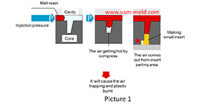
The main reasons for air trapping of plastic injecton mold
Mar 1, 2022During the injection molding process, the front end of the slight ribs may be air trapped and plastic burnt, and also cause the molded part may become black and carbonized. The mechanism of air...view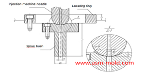
The main design points of the design of the plastic mold pouring system
Jan 11, 2022The main runner is the part where the molten plastic first passes when it is sprayed from the injection nozzle, and it is coaxial with the injection nozzle, because of repeated contact and collision...view
Conformal cooing channel of plastic injection mold
Feb 23, 2022The conformal cooling gate is a new type of mold cooling gate based on 3D printing technolog, because of its processing characteristics, the conformal cooling gate can fit the shape of the product...view
The principle of mold temperature balance in plastic mold cooling system design
Feb 21, 2022The principle of mold temperature balance: 1. Due to the complexity of the plastic parts and mold structure, it is difficult to make the temperature of the mold completely consistent, but should be...view