 English
 русский

The main design points of the design of the plastic mold pouring system
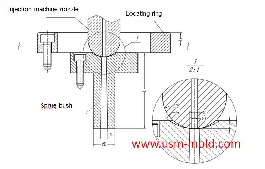
The main runner is the part where the molten plastic first passes when it is sprayed from the injection nozzle, and it is coaxial with the injection nozzle, because of repeated contact and collision with molten plastics and injection nozzles, they are generally not directly installed on the cavity, but are made into detachable sprue bush, which are fixed on the cavity with screws or matching forms, the basic structure of the main runner and the installation type is shown in the following picture.
From the perspective of reducing pressure and heat loss, the conical shape is the most superior sprue shape, the basic size of the main runner usually depends on the following two aspects.
1. The type of plastic used, the quality of the molded plastic part and the thickness of the wall. Generally speaking, for plastics with poor fluidity, the sprue size should be appropriately bigger, and for plastics with good fluidity, the sprue size should be appropriately smaller;
2. The relationship between the geometric parameters of the injection molding machine nozzle and the size of the main runner, in order to prevent the nozzle from contacting the sprue bushing and causing a gap, the spherical radius of the sprue bushing should be 2~5mm bigger than the radius of the nozzle ball, the main runner should have a smooth surface, and the end should be equipped with a cold slug well to prevent the cold slug from flowing into the cavity and affecting the part quality.
In the injection mold, the sprue is in the sprue bushing, and the sprue bushings can be divided into two types: two-plate mold sprue bushing and three-plate mold sprue bushing, the main runner can be divided into two-platen main runner and three-platen main runner according to different mold structures.
The main points of the main channel design are as follows:
1. Using a tapered hole of α=1°~4° to take the condensate of the gate (the cone angle is too big, the injection speed is slow, and the vortex is formed); the inner wall of the tapered hole is rough Ra=0.63μm; the big end of the tapered hole has a transition from R1 to R2 Fillet (to reduce the flow resistance when the material flow turns).
2. The concave spherical surface of the sprue push coincides with the convex spherical surface of the injection machine nozzle: Sr=Sr+ (0.5~2mm injection machine nozzle head radius); d=d1+(0.5~1)m (d1 injection machine nozzle inner diameter) end surface concave spherical depth L2=3~5mm.
3. The outer diameter of the positioning ring D1 is in clearance fit with the positioning hole of the injection machine; the thickness of the locating ring is L1=5-10mm.
4. The length L of the sprue push should be as short as possible (L is too big, the pressure loss is too big, and the temperature of the material is too big);
5. The sprue push material is SKD61 hardened, and the hardness should be less than that of the nozzle of the injection machine.


What is the side parting and core pulling mechanisms with their function?
May 31, 2022When there are holes, cavities or cores on the inside or outside of the injection-molded plastic parts that are different from the opening and closing directions of the mold, the plastic parts cannot...view
Design standard of exhaust slot
Mar 3, 2022The exhaust system should ensure that the gas in the cavity is smoothly discharged, and also prevent the material from entering and exhausting channels from causing flashing of the product or blockage...view
Key points of plastic injection mold runner system
Jan 12, 2022The sub-runner is a transitional channel between the main runner and the gate, as the sub-runner is the longgest part of gating system, so it is very important to enhance the parts quality and improve...view
Slider designing tips 2
Nov 22, 20239. The molding parting surface of the slider molding should be made as a shut-off surface as possible, and the width of the shut-off part should be at least 8mm, and do not make a shut-off surface;...view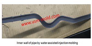
Comparison of water-assisted and gas-assisted injection molding
May 19, 2022Comparing with water-assisted injection molding technology and gas-assisted injection molding technology, the fundamental difference is the nature of the auxiliary molding media used. One is liquid...view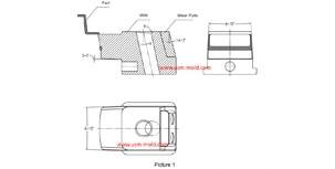
Slider angle designing tips
Dec 4, 20231. Normally, all the insertion slopes of the slider are not allowed to be less than 3° to prevent excessive self-locking force and scratched; 2. The angle of the locking surface must be bigger than...view